ABSTRACT:
This study examines CO₂ capture from the lime production industry using an amine-based absorption process. Through process simulation, the research aims to optimize CO₂ capture efficiency while minimizing energy consumption. Key operational parameters analyzed include the number of trays in the absorption tower, absorption temperature, and reboiler temperature. The findings highlight the impact of these parameters on CO₂ removal efficiency and energy demand. Specifically, the study investigates the correlation between tray count and CO₂ capture performance, as well as the influence of absorption and reboiler temperatures on overall efficiency and energy consumption. By providing insights into the design and operation of CO₂ capture systems in the lime industry, this research supports cleaner production practices and explores potential applications for captured CO₂, contributing to sustainable industrial processes.
Keywords: CO2 capture, lime production industry, process calculation, simulation.
1. Introduction
CO2 (carbon dioxide) is a crucial greenhouse gas. On the one hand, it has negative impacts such as: causing the greenhouse effect, global warming, and climate change; affecting human health; causing ocean acidification, etc. [7]. On the other hand, CO2 has wide applications in many industries such as: the food industry, chemical industry, use in welding and metal cutting, fire extinguishing industry, etc. Therefore, the recovery of CO2 from industrial production activities is very important. In Vietnam, industries emit about 10 million tons of CO2 per year, of which the most are cement, steel, and lime production industry. The lime production process with the main raw materials being CaCO3 and coal emits about 0.78 tons of CO2/1 ton of product [8]. Recovering and producing industrial CO2 from the lime production industry plays a very important role in a green and sustainable production industry. As of now, the total output of lime production units in Vietnam is about 7.4 million tons [8]. However, only a few small units apply the recovery and production of industrial CO2. This causes environmental pollution and waste of resources. Currently, there are four methods of CO2 capture [9]: absorption, adsorption, membrane filtration, and deep cleaning. With outstanding advantages such as high collection and separation efficiency; high product purity; readily available, regenerable, and long-life materials; reasonable cost; no need to change much of the factory structure, easy installation; technology has been commercialized and widely applied, the absorption method has been and is being widely applied. The essence of the absorption method is to use a regenerable chemical solvent which is a weak base (e.g., monoethanolamine (MEA) [7]), the chemical reaction between the base solvent and CO2 (which is acidic) to form a soluble salt solution and then release the absorption to capture CO2 [4, 5, 6]. In the era of Industry 4.0, the application of software to calculate and simulate production processes is very important. The use of simulation helps to improve the design, operation, and optimization efficiency of CO2 recovery systems, contributing to minimizing negative impacts on the environment.
2. CO2 absorption technology using amine
The CO2 capture system includes the following main equipment: Booster fan, absorption tower, desorption tower with heating equipment, MEA heat exchanger; CO2 compressor with CO2 cooler, dry filter tower, CO2 liquefaction unit, liquid CO2 storage tank [4, 5, 7]. The process includes the following steps.
Raw gas washing and pre-treatment:
The exhaust gas from the lime kiln is pressurized by a fan, then passed through a rough gas filter to remove NOx, SO2, and also to cool the raw gas. After water separation, the raw gas is sent to the next part of the cycle.
Absorption and desorption system for CO2 enrichment:
The raw gas from the pre-treatment process is fed into the absorption tower, where CO2 is absorbed in MEA at a temperature of 40°C. The absorption tower is designed as a plate tower, the raw gas is introduced from the bottom of the tower while MEA (lean amine) is pumped in from the top of the tower. The gas stream contacts the liquid stream at the absorption plates. Here, the neutralization reaction of CO2 with amine takes place [1, 3].
|
2HO-(CH2)2-NH2 + CO2 + H2O ↔ (HO-R-NH3)2CO3 |
(1) |
The temperature in the absorption tower is maintained from 30 to 50°C and at high pressure. High temperature or low pressure will increase the flow rate of the liquid amine, thereby reducing absorption efficiency. In addition, low temperature will also increase the efficiency of the absorption reaction (because the neutralization reaction is an exothermic reaction).
After the absorption process is the desorption process to recover CO2 and regenerate the solvent. The CO2-rich amine (rich amine) taken from the bottom of the absorption tower is passed through a heat exchanger, where the CO2-rich amine stream will exchange heat with the hot amine stream from the desorption tower to be preheated to reduce the heat consumption of the system. Then the rich amine stream will be pumped to the top of the desorption tower. The following reaction will occur here:
|
(HO-R-NH3)2CO3 ↔ 2HO-(CH2)2-NH2 + CO2 + H2O |
(2) |
The desorption reaction is endothermic, so it is necessary to maintain high temperature and low pressure for the desorption tower. The temperature is usually maintained in the tower from 115 to 126°C and the pressure from 1.4 to 1.7 bar at the bottom of the tower. To maintain the temperature, a heater is placed at the bottom of the tower to heat the amine mixture. The amine after desorption (lean amine) is pumped back to the heat exchanger and to the top of the absorption tower.
Compression and cooling:
The CO2 gas coming out from the top of the desorption tower is cooled by a cooler and washed through a water scrubber. Then CO2 is passed through a water separator and impurity filter. The gas coming out from the water scrubber is fed into the compressor. After three compression steps, the gas pressure reaches 28 bars, and the gas is transferred to the next step.
Drying:
The gas from the compressor is fed into the drying system. The drying system consists of two Zeolite molecular sieve columns. One column is used for drying, the other for regeneration. The switching time is eight hours. After the drying system, there is a filter unit of the molecular sieve.
Liquefaction and storage:
After the drying step, the gas is fed into the liquefaction unit, where the CO2 gas will be liquefied in the condenser at a temperature of -30°C to -32°C. The liquid CO2 product with a purity of 99.95% to 99.98% CO2 will be stored in specialized storage tanks at a temperature of -23°C to -25°C at the product warehouse. Liquid CO2 will be filled into bottles or pumped into tanks placed on specialized vehicles for transportation to the place of consumption.
3. Simulation of CO2 capture from lime production industry
3.1. Model setup
Simulation is performed using Aspen HYSYS software to simulate the absorption and desorption process to remove CO2 using MEA solution. The processes are countercurrent. The kinetic model is the Kent Eisenberg model [6]. The calculation method is based on Murphree efficiency [1, 2, 3]. The process flow diagram and simulation process are shown in Figure 1.
Figure 1. (a) Process flow diagram (b) Simulation of the absorption process
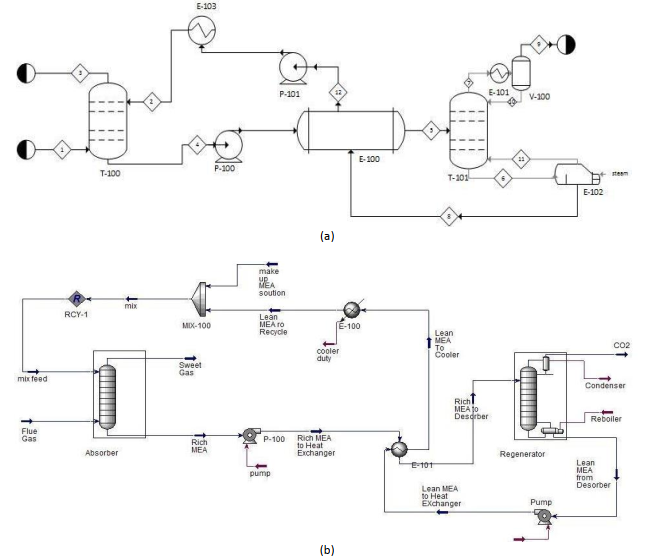
Source: Analysis by authors
3.1.1. Input parameters
The input parameters are shown in Table 1.
Table 1. Input Parameters of the gas flow and liquid flow
|
Unit |
Value |
|
|
Inlet gas temperatue |
ºC |
40 |
|
Inlet gas pressure |
bar |
1.1 |
|
Inlet gas flow |
kmole/h |
85000 |
|
CO2 in inlet gas |
mole-% |
22 |
|
Water in inlet gas |
mole-% |
3 |
|
Lean amine temperature |
ºC |
40 |
|
Lean amine pressure |
bar |
1.1 |
|
Lean amine rate |
kmole/h |
120 000 |
|
MEA content in lean amine |
mass-% |
29 |
|
CO2 in lean amine |
mass-% |
5.5 |
|
Number of stages in absorber |
|
10 |
|
Murphree efficiency in absorber |
|
0.25 |
|
Rich amine pump pressure |
bar |
2 |
|
Heated rich amine temperature |
ºC |
104.5 |
|
Number of stages in stripper |
|
6 (3 + 3) |
|
Murphree efficiency in stripper |
|
1.0 |
|
Reflux ratio in stripper |
|
0.3 |
|
Reboiler temperature |
ºC |
120 |
|
Lean amine pump pressure |
bar |
2 |
|
Minimum deltaT in heat exchanger |
ºC |
10 |
Source: Analysis by authors
3.1.2. Input gas flow
The composition of the input gas flow to the absorption tower is presented in Table 2.
Table 2. Composition of the input gas flow
|
Composition |
Concentration (% v/v) |
|
CO2 |
0.22 |
|
N2 |
0,65 |
|
O2 |
0,07 |
|
H2O |
0,03 |
|
CO |
0,02 |
|
SO2 |
54 mg/m3 |
|
H2S |
9.3 mg/m3 |
Source: Analysis by authors
3.1.3. Input liquid flow
The composition of the input liquid flow to the absorption tower is presented in Table 3.
Table 3. Composition of the input liquid flow
|
Composition |
Concentration (% w/w) |
|
CO2 |
0.055 |
|
MEA |
0,29 |
|
H2O |
0,655 |
Source: Analysis by authors
3.2. Results and discussion
The simulation can be done in two ways. The first is to keep the % of CO2 absorbed constant to determine the heat consumption as well as the number of trays of the tower. From there, optimize the balance between operating costs (heat consumption) and investment costs (number of trays or tower height). The second is to determine the amount of CO2 absorbed and the amount of heat consumed in the desorption process with known input parameters.
3.2.1. Number of trays in the absorption tower
The height of the absorption tower can be changed by changing the number of trays. The Murphree tray efficiency factor for CO2 is kept constant at 0.25 [1, 2]. The height can also be changed by changing the tray efficiency factor. Efficiency increases and heat decreases as the tower height and number of trays increase. The optimal theoretical number of trays is 12. The results are shown in Figure 2.
Figure 2. The relationship between CO2 removal (%), number of trays and heat consumption
Source: Analysis by authors
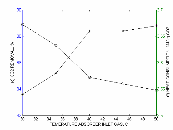
3.2.2. Absorption Temperature
Increasing the inlet temperature of the gas and liquid leads to a decrease in absorption efficiency and an increase in energy consumption. The optimal temperature is around 40°C. The simulation results are shown in Figure 3.
Figure 3. The relationship between CO2 removal (%), absorption temperature and heat consumption
Source: Analysis by authors
3.2.3. Absorption pressure and desorption pressure
The absorption pressure is maintained at 1.1 bar. The desorption pressure is maintained at 2 bars.
3.2.4. Reboiler temperature
Increasing the heater temperature increases the concentration of the amine solution and improves the CO2 removal efficiency. However, if the temperature increases above 120°C, the amine will decompose. There was an "outside range" warning when running the simulation at a temperature of 121°C. The calculation results in the temperature range of 118 ÷ 120°C are presented in Figure 4.
Figure 4. The relationship between CO2 removal (%), reboiler temperature and heat consumption
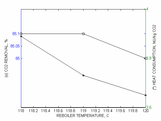
Source: Analysis by authors
4. Conclusions
This study has presented an overview of the CO2 capture absorption process from the lime production industry. By performing simulation calculations, it has provided an overview of the relationships between tower geometry, technological and operational parameters (heat consumption). From there, balancing investment costs and operating costs to optimize the process. The use of simulation software offers many benefits such as process optimization, equipment design and evaluation, economic analysis, etc. From the research results, it can be extended to problems in other production sectors such as cement production, steel production, coal-fired power plants, and the petrochemical industry.
REFERENCES:
[1] Alie C., Backham P., Croiset E., Douglas P.L.(2005). Simulation of CO2 capture using MEA scrubbing: A flowsheet decomposition method. Energy Conversion & Management, 46, 475-487.
[2] Desideri U., Alberto P. (1999). Performance modelling of a carbon dioxide removal system for power plants. Energy Conversion & Management, 40, 1899-1915.
[3] Freguia S., Rochelle G.T. (2003). Modelling of CO2 Capture by Aqueous Monoethanolamine, AIChE Journal, 49, 1676-1686.
[4] Kent R.L., Eisenberg B. (1976). Better data for Amine Treating. Hydrocarbon Processing, 55(2), 87-90.
[5] Lee I.J., Otto F.D., Mather A.E. (1975). Solubility of Mixtures of Carbon Dioxide and Hydrogen Sulfide in 5.0 N Monoethanolamine Solution. Journal of Chemical & Engineering Data, 20, 161-163.
[6] Peng D., Robinson D.B. (1976). A New Two Constant Equation of State. Industrial & Engineering Chemistry Fundamentals, 15(1), 59-64.
[7] Tobiesen F.A., Svendsen H.F., Hoff K.A. (2005). Desorber energy consumption amine based absorption plants. International Journal of Green Energy, 2, 201-215.
[8] Nghiem Gia (2019). Recovery of industrial lime kiln emissions to produce liquid CO2 is an effective solution to eliminate artisanal lime kilns in Vietnam. Environmental Magazine, 3/2019 (in Vietnamese).
[9] Versteeg G.F., Van Dijck L.A.J., Van Swaaij W.P.M. (1996). On the kinetics between CO2 and alkanolamines both in aqueous and non-aqueous solutions: An overview. Chemical Engineering Communications, 144, 113-158.
Tính toán mô phỏng dây chuyền công nghệ thu hồi CO2 từ sản xuất vôi bằng phương pháp hấp thụ amine
Phạm Hoàng Dương1
Nguyễn Trung Dũng1
Vũ Hồng Thái1
1Khoa Kỹ thuật Hóa học, Trường Hóa và Khoa học Sự sống, Đại học Bách khoa Hà Nội
TÓM TẮT:
Nghiên cứu trình bày các kết quả nghiên cứu thu hồi CO2 từ sản xuất vôi bằng phương pháp hấp thụ sử dụng dung môi amine. Sử dụng phần mềm mô hình hóa để mô phỏng quá trình hấp thụ và giải hấp nhằm tối ưu hóa hiệu quả thu hồi CO2 và giảm thiểu tiêu thụ năng lượng. Các thông số chính được nghiên cứu bao gồm số lượng đĩa của tháp hấp thụ, nhiệt độ hấp thụ và nhiệt độ gia nhiệt lại. Kết quả nghiên cứu cho thấy ảnh hưởng của các thông số này đến hiệu quả loại bỏ CO2 và tiêu thụ nhiệt. Đó là mối quan hệ giữa số lượng đĩa của tháp và khả năng loại bỏ CO2, cũng như ảnh hưởng của nhiệt độ hấp thụ và gia nhiệt lại đến hiệu suất thu hồi và tiêu thụ năng lượng. Các kết quả nghiên cứu có thể ứng dụng cho việc thiết kế và vận hành hệ thống thu giữ CO2 trong ngành sản xuất vôi, cân bằng chi phí vốn và chi phí vận hành để đạt hiệu suất tối ưu, giảm thiểu lượng phát thải CO2, bảo vệ môi trường và phát triển bền vững.
Từ khóa: thu hồi CO2, công nghiệp sản xuất vôi, dây chuyền, sản xuất vôi, amine.
[Tạp chí Công Thương - Các kết quả nghiên cứu khoa học và ứng dụng công nghệ, Số 5 tháng 2 năm 2025]